The Thorlabs reflective fiber collimator is based on a 90°off-axis paraboloid (OAP) mirror with a constant focal length over a wide wavelength range and is ideal for use in systems requiring collimation of multiple wavelengths.
The reflective collimator is available in three housing designs, each compatible with fiber jumpers with FC/PC, FC/APC, or SMA connectors.
Basics Of OAP Reflector
OAP(Off-Axis Parabolic) Reflector is a part of its parent parabolic.
Off-axis means that the optical axes of the two are parallel but not coincident.
The focus axis passes through the center of the focus and the OAP Reflector, and the distance between these two points is called the reflected focal length (RFL).
The Angle between the focusing axis and the optical axis is the off-axis Angle, which is 90 degrees here.
Fixed Collimator
Fixed fiber collimators provide two high reflectivity metal films: -F01 UV- enhanced aluminum film and -P01 silver film with protective layer, which are recommended for single-mode and multimode fiber collimation and multimode fiber coupling applications.
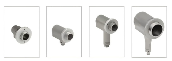
According to the collimated beam diameter (for 0.13 NA fiber), they can be divided into the following four series:
The four pictures above are RC02FC-P01, RC04FC-P01, RC08APC-P01 and RC12SMA-P01 respectively.
Therefore, according to the product model, we can know the main parameters of each reflective collimator, including collimated beam diameter, fiber connector and coating.
The RC02, RC04, and RC08 collimators are compatible with internally SM05-threaded mounts, while the RC12 collimator is compatible with internally SM1-threaded mounts.
In addition, the RC02 collimator can be end-mounted directly into a Ø1/2" kinematic mount, while the RC02, RC04, and RC08 can be end-mounted directly into a Ø1" kinematic mount (after first unscrewing the knurled ring on the freespace port);
Mounting with a kinematic mount facilitates beam alignment when fiber coupling is required.
Small Collimator
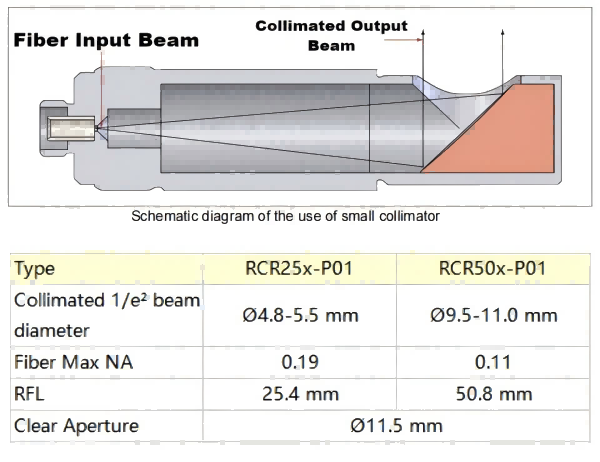
The small collimator achieves a slimmer design by having the reflector in the opposite direction to the front. It can be divided into two series according to the focal length: RCR25x-P01 and RCR50x-P01, with reflection focal lengths of 25.4 and 50.8 mm respectively; the x in the model number is the fiber connector type, which can be substituted with P, A and S to represent FC/PC, FC/APC and SMA connectors respectively.
Small collimators can be mounted directly into Ø1/2" lens tube mounts, such as the SM05RC(/M) slip ring and SM05TC clamp.
If pitch/yaw adjustment is required, they can be mounted in a Ø1" kinematic mount using the SM1A60 adapter.
The small collimator can also be integrated directly into a 16 mm cage system using an SP3 cage plate or SC6W cage cube, or into a 30 mm cage system using an SM1A60 adapter and a C4W cage cube.
Adjustable Collimator
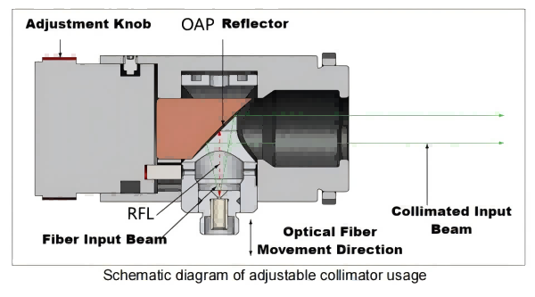
Adjustable collimators can adjust the distance from the fiber to the OAP mirror to optimize the collimation of each fiber or to couple light into singlemode or multimode fibers.
When the scribed line is aligned with the ∞ symbol, the distance from the fiber to the OAP reflector is equal to the RFL, and the collimator outputs a collimated beam (above).
When the scribed line deviates from the ∞ symbol, the collimator outputs a divergent or convergent beam, and the maximum distance from its focus to the center of the reflector is -2.2 m and 0.15 m, respectively, as shown in the following two figures.
When the conjugate ratio is equal to infinity, OAP mirrors can achieve diffraction-limited imaging.
As shown in the figure below, two adjustable reflective collimators are also very suitable for long-distance coupling, so that the intermediate free-space beam can be steered with other optical elements, which is very useful in long-distance communication applications.
The RCF15x-P01 adjustable collimator can be mounted in an SM1RC(/M) slip ring or SM1TC sleeve clamp using the black section.
For pitch/yaw adjustment, it is recommended to use a Polaris mount, such as the POLARIS-K2 or POLARIS-K2VS2L Ø2" kinematic mount using the AD2T adapter; the POLARIS-K2T SM2-threaded kinematic mount using the SM2A21 adapter; or the POLARIS-K15XY 5-axis kinematic mount using the SM1L03 lens tube and SM1A68 adapter.
The free-space end of the adjustable collimator housing is threaded with internal SM05 and external SM1 threads.
Examples of mounting the collimator are shown in the following two figures.
Single Mode Fiber Collimation
When collimating single-mode fibers, these reflective collimators produce wide-waist, low-divergence beams.
The total divergence of a collimated beam (in degrees) can be approximated by the fiber mode field diameter (MFD) and the reflector focal length (RFL):
The 1/e² diameter of a collimated beam is approximately:
For example, using the RCR25A-P01 small collimator to collimate the P3-630A-FC-1 single-mode fiber, at a wavelength of λ = 633 nm, the MFD is 4.3µm.
The above two equations show that the divergence angle is 0.01 degrees, and the beam diameter is 4.8 mm.
Multimode Fiber Collimation
The total divergence angle of a collimated beam is approximately:
The diameter of the collimated beam is approximately:
The output of multimode fiber is usually not well collimated.
According to the above formula, the beam diameter is mainly affected by NA at a position close to the OAP reflector, but as the beam propagates, the influence of the core diameter becomes more and more obvious.
For the fixed collimator mentioned above, the collimated beam diameter is calculated by 2NA*RFL, which is greater than 1/e² beam diameter.
When choosing a fixed collimator, the focal length can be inferred from the required beam diameter to determine the appropriate model.
There are two important limitations to collimating multimode fibers.
First, most multimode fibers have a very divergent output beam that can be blocked by the housing before reaching the OAP reflector, so the fiber NA cannot exceed a certain value; see the previous table for details.
Second, the divergence of the collimated beam is related to the core diameter; as the core diameter increases, the maximum NA supported by the collimator decreases.
If the collimated beam diameter exceeds the clear aperture, the output beam will be blocked by the housing.
Both of these situations can lead to reduced beam quality.
In addition, OAP reflectors can only perfectly collimate point sources at the focal point.
The greater the deviation of the point source from the optical axis, or the larger the multimode core diameter, the greater the distortion of the collimated beam; increasing the reflection focal length or wavelength can reduce the distortion.
Post time: Nov-05-2024


